How to improve the chiller system efficiency during design stage?
We discussed earlier how to maximize the energy saving by relacing an old chiller in retrofit projects but in the these projects you are stuck with the existing chilled water system and the limited spaces in the building and you need to find ways to improve the existing system with the constraints available on site. On contrary, for new projects, you have the privilege to design and specify efficient chiller system from early stages and you can compare and analyse different system options and select the one that has the best life cycle cost.
In this article we discuss some ways to improve the efficiency of the chiller system during the design stage, however, the designer should analyse the designed system in a holistic approach to make sure they select the best system that meets the project budget and achieve the best possible efficiency.
- Chiller:
As we mentioned earlier in our previous article, the chiller should be high efficiency variable speed chiller with magnetic bearing compressors are the best. Air cooled chillers should have EC fans for the condenser and should be equipped with adiabatic system to improve their efficiency further.
- Chiller Leaving Chilled Water Temperature:
The chiller efficiency depends on the compressor lift, which is the difference between the suction and discharge pressures. The smaller the difference in pressures the higher the efficiency of the chiller. The pressure is proportional to the temperature and therefore, the compressor lift and then the chiller efficiency depends on the leaving chilled water temperature and the leaving condenser water temperatures for the water cooled chillers or the leaving air temperature for the air cooled chillers.
Based on the above, we can see that increasing the leaving chilled water temperature from the chiller will improve its efficiency. As a rule of thumb, for every 1°C increase in leaving chilled water temperature, there is 3% reduction in chiller energy consumption. Therefore, always design your system with high leaving chilled water temperature. Note that increasing the chilled water temperature leads to bigger coils in the AHU’s and FCU’s and therefore, the designer should carry out life cycle cost analysis to select the optimum system.
The designer should also consider selecting chilled beams or displacement diffusers for the chilled water system because these types of systems require higher chilled water supply temperature that can reach 16°C. This high chilled water temperature allows you to select smaller chillers and in the same time improve the chiller efficiency.
- Reducing Pumps Flow Rate:
Most of the engineers design the chiller system at 5°C delta T on both the chilled water side and also on the condenser side if the chiller is water cooled. This is the old way to design the system but due to the need for energy efficiency, we need to increase delta T to 8 – 10°C to reduce the flow rate so we can select smaller pumps and save in the pumping energy. Further, reducing the condenser water flow rate for the water cooled chillers, will leads to smaller cooling tower and smaller tower fan, which also reduce the energy consumption further. Not to forget to mention that reducing the water flow rates leads to select smaller pipes, which reduces the capital cost of the project.
- Water Cooled Chillers Connection Configuration:
We still see in most of the projects the water cooled chillers connection is parallel, while there is another configuration that makes these chillers more efficient specially for the large capacity chillers.
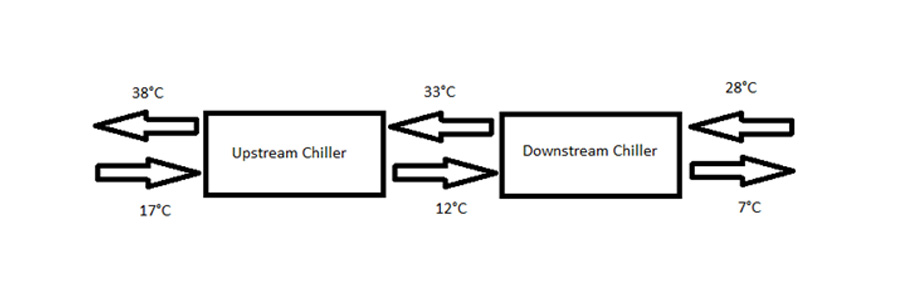
Series counter-flow chillers configuration as shown in the figure below reduces the chillers lift and improves their efficiency. You can see from the figure below that the chiller that has lower leaving chiller water temperature has also the lower leaving condenser water temperature and vis versa. This configuration makes both chillers see approximately the same smaller lift (26°C) than seeing the bigger lift (31°C) if they are both connected in parallel. Chiller manufacturers claim that this configuration can improve the chiller efficiency by up to 13%.

- Using Variable Speed Drives (VSD):
Motor energy consumption is proportional to the cube of the flow rate and therefore, reducing the water or air flow rate will reduce the energy consumption of pumps and fans drastically. Thus, the followings should be specified with VSD:
- Chilled Water Pumps with emphasis on variable primary flow configuration, which saves on the initial and running costs.
- Condenser Water Pumps
- Cooling Tower Fans
- Air Handling Units Fans
- Using Pressure Independent Control Valves (PICV):
Using pressure independent control valve for the air terminal units such as FCU’s and AHU’s is much better than using the traditional combination of the 2-way control valve and balancing valve. The 2-way control valve change the flow rate supplied to the terminal unit based on the pressure difference between its ports. This means that many times this 2-way valve will allow more water flowrate to the terminal unit than what is required. This overflow reduces the return chilled water temperature to the chiller and causes what we call it low delta T syndrome. This reduces the chiller efficiency and leads to more chillers to run, which increase the chillers energy consumption and reduce the system efficiency. Further, this overflow makes the pumps run at higher speed to meet the required overflow, which also increases the pumps energy consumption.
On contrary, PICV maintains the required flow rate to the terminal units regardless what is the pressure difference between the two ports. Therefore, it eliminates the overflow to happen and make the system more efficient.
- Thermal Storage Tanks:
Thermal storage tanks whether it is chilled water, ice or phase change material (PCM) can be used to shift the electricity demand from the peak time to other times to reduce the peak demand charges. However, these tanks occupy big area in the building and not always it is possible to accommodate them. The largest tank is the chilled water storage tank and the ice tank requires around 20% of the volume of the chilled water tank for the same thermal capacity, while the phase change material tank requires 50% of the volume.
The chilled water thermal storage tank is the easiest option to include in the design but because of its large volume, it is not always practical to include it.
The ice conductivity is low and requires low operating temperatures, which reduces the chiller efficiency and therefore, can be used for demand shifting but for energy efficiency, a more detailed analysis should be done to make sure that operating the chillers at low ambient temperature during the night for example will outperform the reduction in efficiency due to the low chilled water temperatures.
The most common material used for PCM tanks is Eutictics and this material has freezing point of around 8.3°C, which make it the best option to choose for chilled water systems to save energy, however, the size of the tanks still a challenge to include it in the building.
- Controls:
The building management system (BMS) should be designed and specified well and should include energy efficiency control strategies to make the chiller system operation more efficient. Below are examples of energy efficiency control strategies that should be included in the BMS:
- Chilled Water Temperature Setpoint Reset. Note that this strategy conflicts with the variable speed chilled water pumping strategy and therefore, it is more suitable for constant flow systems and for variable primary flow systems the precedence should be for the variable speed pumping and after the flow is at minimum, then the chilled water temperature setpoint reset should apply.
- Condenser Water Temperature Setpoint Reset.
- Optimum Start/Stop
- Demand Limiting
Further, the designer should specify Chiller Plant Optimization Controller, which is a controller dedicated only for the chiller plant (chillers, cooling towers, pumps and valves) and has algorithms to optimize the planet water temperatures and flows to make sure the plant equipment operate at their maximum efficiency.
For an energy efficiency design review for your chiller system and other building services design to improve it and make it more efficient, then please contact us.
Ahmed Refaie
Thanks Ahmed for this valuable article, just to some points came to my mind while reading
1-The chiller with high capacity will be very low expensive if it is VSD
2-Usually the TES tanks are economical when plant capacity exceeds 10,000 TR and it also depend on the nature of load profile
3- I think 5 degree Celsius is superseded l, as all designs I did or see from other companies come with 6.7 Celsius for ACC and 8.9 for WCC
4- My experience with series flow configuration that when a chiller is off due to maintenance or trip, the there will be higher supply chilled water temperature and higher mix temperature in the header, so it is effective when you have a mega scale plant
adminaes
Thanks Ahmed for these comments. Please find our reply to these comments below:
1- This article was written for Australia Market where most of the chillers in the commercial buildings are powered by low voltage and not medium voltage as you have in the projects of the Middle East. VSD for low voltage power supply is competitive and it has high return on investment if included with the chillers.
2- Chilled water TES is more economic for the large systems because it has large size but the ice and the phase change material tanks are suitable for smaller projects because they are effective to shift the electrical demand from the peak time to the off peak time to reduce peak demand charges and also to reduce the stress on the electrical network.
3- 5°C delta T should be superseded and we should start considering larger delta T to save energy. However, we still see many projects designed with 5°C delta T specially for small projects.
4- It is true that series-counter Flow arrangement is more suitable for large chillers and this is what we referred to in our above article but still can be implemented for smaller chillers if you have more than two chillers considering that if a pair of chillers are off for maintenance, then the other pair of chillers will provide part of the cooling until the faulty chillers are fixed and running.
Regards
Ahmad Fraij
Ahmed Refaie
Sorry point #1 I meant chillers with high capacity will be with MV electrical connection in most of the cases so it will be very costly to consider VSD starter
Ahmed Refaie
Thanks Ahmed for this clarification and this informative article